These pages cover questions I have been asked and expand on my replies
Injectors. How do they work inside ?
Looking inside an injector you will find there is a lot less going on than you might have thought. The body of the injector is largely empty, being simply an extension tube to position the tip in the correct place in the head. The working parts of the injector comprise, working from the top down, a fine filter. This is set into a reducer block so as to form a small gap behind the filter mesh. The block itself has a hole in the centre leading to the delivery tip below. The working element of the injector is in the form of a spring loaded plug. This is seated into a tapered seating. The plug itself is also tapered to the underside to correspond with this seat. The plug is formed with a shaft leading back into the injector and passed through an inner seat against which the spring is loaded. The spring is in compression keeping the plug tight against the outer seating. When fuel is passed into the injector under pressure the inner seat is pushed against the spring allowing the plug to move outwards opening the injector. Then when the pressure drops in the injector the plug closes and seals to the outer seating. The taper provided between the plug and the outer seat is formed so as fuel passing between the tapered surfaces is formed into a conical fan to the same angel as the taper. It is this that forms the spray pattern of fuel in the cylinder head.
Common problems with the injectors are:
- Blockage of the filter
- Uneven spray pattern
- Plug not opening at the correct pressure
- Plug not sealing when closed
Blockage of the filter is corrected by deep cleaning the injectors using an ultrasonic tank. I have found that nothing else will do the job. Uneven spray pattern is as a result of dirt on the seat taper. This is normally corrected by cleaning but the seat can be worn making replacement necessary. Plug not opening at the correct pressure is due to either dirty fuel deposits in the injector preventing the plug moving freely. This can result in the injector not opening until 3000psi or more. As the pump cannot generate these pressures the injector often simply does not deliver any fuel. Opening too early is also a problem as it will result in uneven delivery as the pump is calibrated to run with the injectors opening at the correct pressure. This is often due to the spring being tired and having lost its tension. Plug not sealing when closed. This is due to either dirt again in the seating taper, wear to the taper or a weak spring. Try cleaning first but if the holding pressure is not resolved you will need to replace it. A poor spray pattern will result in poor running as the fuel will not be correctly atomised in the airstream. An injector not opening correctly will result in either no fuel delivery or a poor spray pattern An injector not closing will result in loss of pressure in the fuel lines. This causes misfiring due to uneven fuel delivery and poor starting.
Injector testing
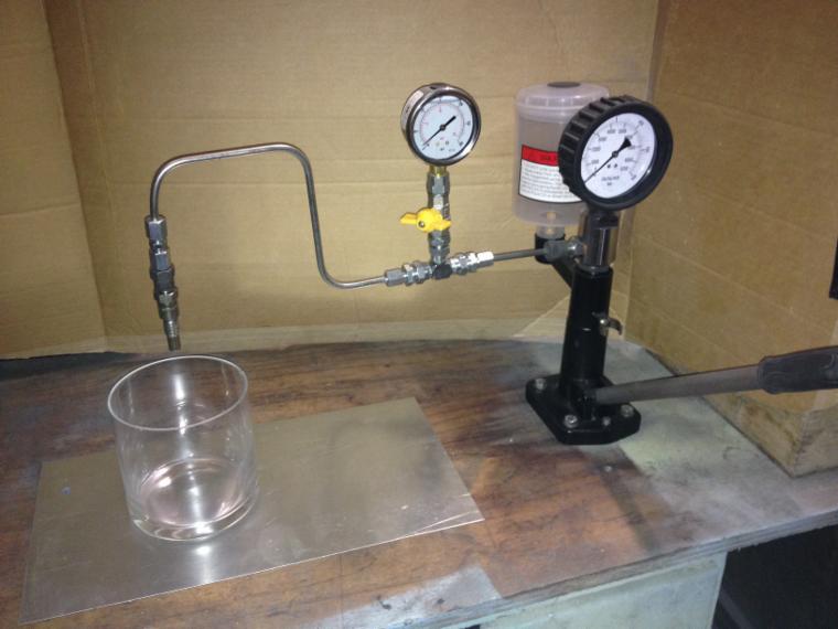
I use this Sealey test rig that I have modified to incorporate a gauge so I can read the holding pressure as well as the pop to a more accurate level as the standard gauge is calibrated for diesel injectors. When tested the injectors should open between 200- 250psi. As the pressure drops off it should close at around 150psi and hold 150psi indefinitely with no drop off at all. The spray pattern should form an even conical spray at 9 degrees from the vertical all round (ie 18 degrees total spread) I find that around 60% of injectors I test do not meet the required specification. Ones with only a slight drop off in pressure can be used but it’s really best just to replace them as a matter of course despite the cost.
Can you explain how the pistons work?
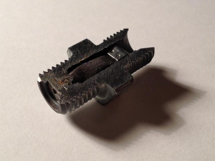
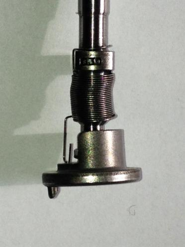
Let’s consider how the piston arrangement works on a MFI pump. The piston barrel sits in the pump body with the head in the fuel holding chamber whilst the tail end of the barrel extends down below the chamber into the rack area. A seal is formed between the underside of the head and the pump casting by the mating machined faces of the barrel head underside and the pump casting. You can see this when the barrel is removed as a seat cut in the casting with a corresponding machined face on the underside of the barrel head. It is this seat that tends to leak over time allowing fuel to pass into the oil chamber of the pump. Once fuel starts to pass through the seat a grove is eroded in the pump casting making it difficult to reseal the barrel. The head of the barrel has two holes in the sides, the higher one of which to the rear allows fuel to flow into the barrel. Further down there is a capillary groove cut to prevent fuel passing down the piston shaft into the pump oil.
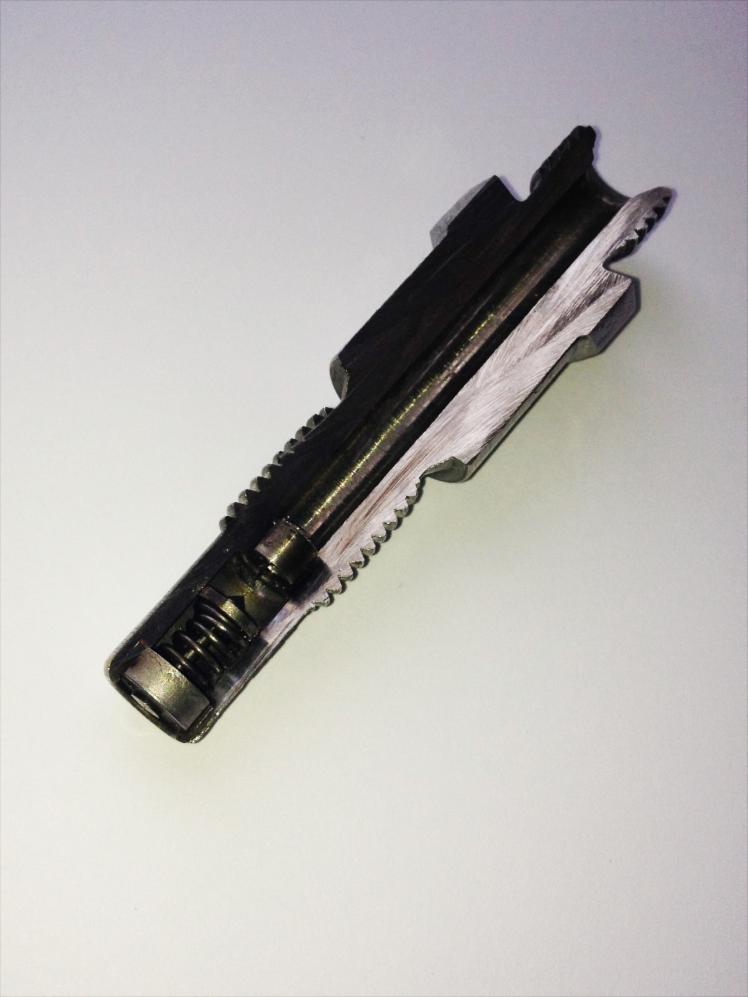
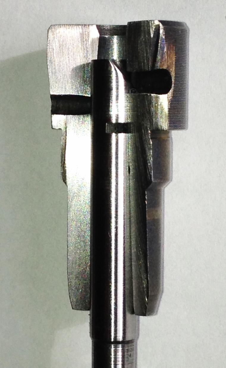
The piston itself comprises a shaft cut with a helical groove at the top and a cross- slot cut in the shaft below this. The cross cut is exposed to the fuel chamber momentarily at TDC so the fuel can be used to pre-load the barrel, lubricate and cool the piston, excess pressure in the lubrication system being vented by the front lower hole. At the base of the shaft there are lugs to the front and back used to fix the shaft to the clamping sleeve. Just below the lugs a tip is formed with a flattened end to attach the shaft to the spring seat. Whilst the lugs are the same front and back the piston can only be fitted facing one way so the lugs are marked. On one side you will see three numbers. This is the clearance measured between the piston and the barrel, in this case 0.030mm. These markings face out when the piston is correctly orientated.
The helical groove at the top of the shaft is referred to as the metering land. The alignment of this groove with the hole in the barrel determines how much fuel is delivered, changing as the land rotates relative to the barrel. From the section you can see the helical grove crosses the rear hole at an angle, dissecting the opening. The grater the fuel demand on the pump the earlier the grove appears in the hole exposing the land to fuel flow and the larger the opening. Conversely as the pump retards towards stop the land appears in the opening for a shorter and shorter period of time and with a smaller opening area. Due to fluid dynamics allowing the fuel only to pass through the opening at a fixed rate at a given fuel supply pressure, this results in less flow onto the land. This is why it is important that the supply pressure of fuel to the MFI pump is correctly controlled.
When the pump is at stop. The piston is rotated so as the helical grove just about closes the hole off through the majority of the stroke, although some flow is provided to maintain idle. Rotational movement of the piston is achieved by clamping the piston into a sleeve with the gear segment. The delivery of each piston relative to the others can be changed by making changes to the position the piston are clamped into these sleeves. The degree of adjustment needed to change the delivery is tiny. This is done by undoing the clamping gear segment and turning the sleeve by putting a pin in one of the holes provided and using this as a lever to rotate the sleeve.
Each piston is fitted with a small return spring. These acts to rotate the pistons towards the full flow position at any given setting. In this way the pump is always ready to deliver fuel at the maximum level the governor will allow at any given RPM. Runaway fuel delivery is of course controlled by the flyweights constantly fighting back the other way trying to retard the delivery. The pistons are driven up and down by the drive cam. This pushes the rollers and in turn moves the pistons which are returned to their lowered position at the end of each stroke by the large piston return springs.
So to summarise, variation in the delivery of the pistons is achieved by varying the duration to which the metering land is exposed to fuel flow through the hole in the barrel head and the size of the opening provided. This is achieved by rotating the helical groove relative to the hole so the land is exposed as the piston drops for a greater period when a rich mix is required and for a shorter period when a lean mix is needed.
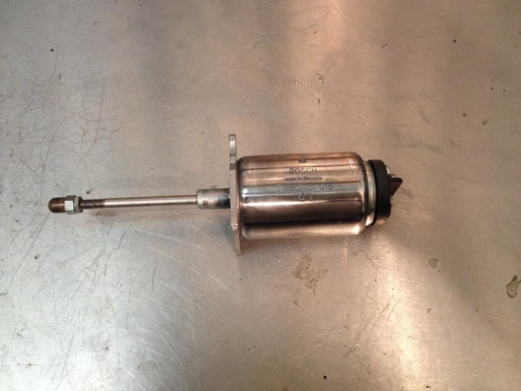
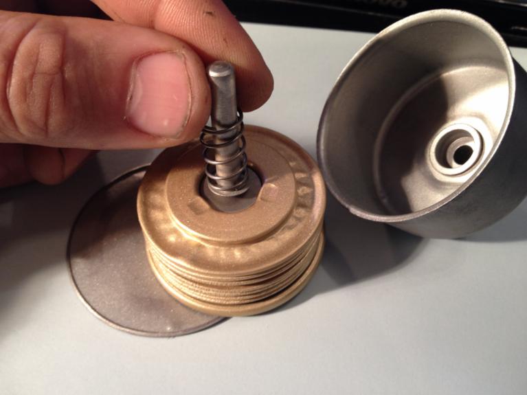
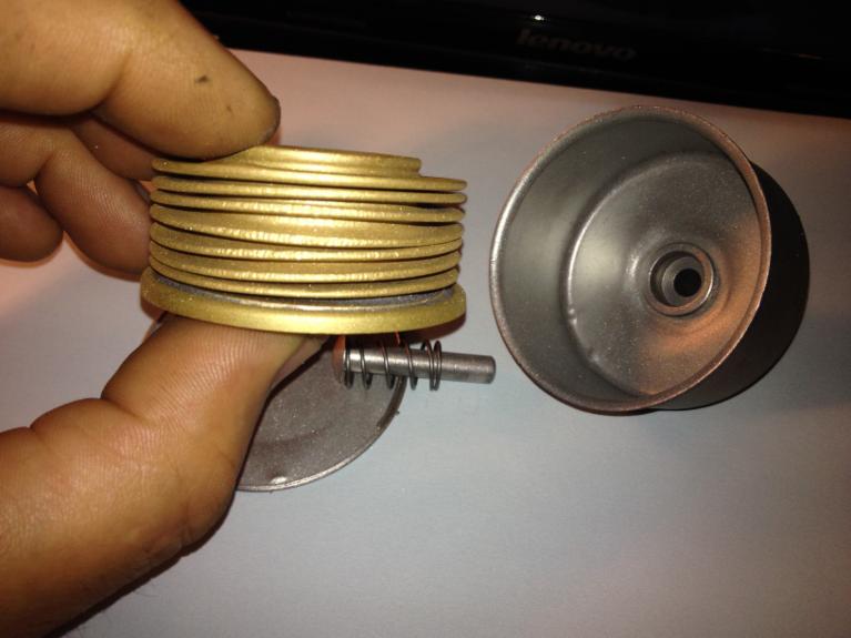
Can I take my solenoid apart to fix it? Let’s look at how the solenoid is put together and how it works.
The outer casing from the mounting plate to the back end of the unit is formed as one piece with access to the internal parts being from the back end where the casing is rolled over locking the end cover in place against a sealing washer.
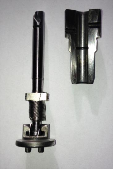
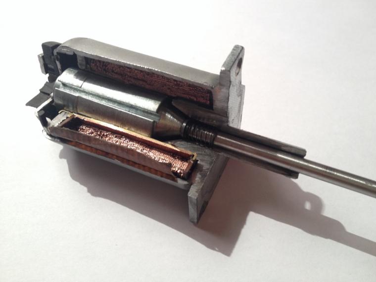
From the cutaway you can see that the central rod is formed with a cylindrical piston within the solenoid body. A spring is provided to the rod pressing against a seating washer. This spring returns the rod to its deactivated position when the power supply is switched off. The piston has a groove cut down its length to allow oil to pass from the pump through the unit to provide lubrication.
The piston runs in a brass lining around which copper wire is wound forming the electromagnetic field. This copper winding is wrapped in an insulating paper wrapping. The brass liner is held from moving by splines cut on the inward projection of the main casing. The projection is also tapered internally to match a taper formed on the piston so as to form a large contact surface area when the solenoid is activated.
At the front end of the winding an insulator washer is provided to separate the winding from the casing with a similar arrangement at the back end seated against the large centring washer that doubles as the seating for the back cover. The inside face of the back cover has an insulator pad against which the piston seats when in the deactivated position.
Electrical connection from the back cover is taken to the winding whilst being insulated from the casing by the Bakelite plate.
When a current is applied to the winding the piston is driven forward by the electromagnetic field created. The distance the rod is pushed is always the same, adjustment of the rod action being made by narrowing or increasing the clearance between the rod and the pump stylus arm by winding in or out the dome nut on the end of the rod. A locking nut is provided to secure the dome nut in the right position. The dome nut has a rubber cover to deaden the striking of the rod against the stylus arm. The rod is correctly adjusted when it moves the rack by between 1.00 – 2.00mm. This is set during testing by checking the movement with a dial test indicator.
So is the solenoid repairable? Yes, but only by cutting them open and then welding them up after repair.
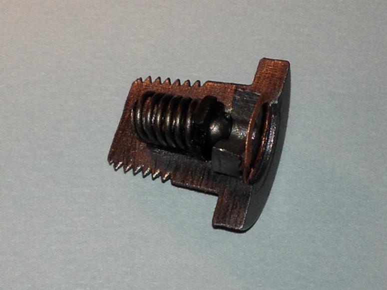
If you have ever wondered how the non-return valves on the top of the pump work take a look at the cutaway below. You can see that there is a strong steel spring at the top of the valve. This presses down on a spring cap formed with three cutaways to allow the fuel to flow past. The spring cap in turn presses against a steel ball bearing, holding the bearing tightly against a taper in the seat. The seat itself is a thick steel disk and is sealed into the casting with a brass ring.
The early 2.0lt valves have a small 3mm ball bearing while the later valves from 2.2 onward are larger.
When the valves fail it is normally due to dirt inside the valve preventing the bearing seating correctly. This can be corrected by cleaning the valves in a ultrasonic tank as described in my book. However if the bearing or seat disks are corroded they will not seal correctly and the valves will leak resulting in loss of back pressure in the fuel lines and the valves must be replaced.
The valves are assembled by press deforming the outer body after the disk and sealing brass ring are installed so the valves can’t be taken apart to clean them or replace the bearing.
How does the oil feed into the pump and what is the bit of metal stuck inside the oil feed fitting for ?
The lubrication oil for the injection pump is taken from the engine under pressure. The feed is taken to the fitting on the right side of the pump where oil is fed into the pump body. The oil enters the pump via the follower bore for number 3 cylinder and runs down into the sump from there. The oil feed is not pressure fed to the other followers or the pistons. The oil builds up in the pump and finds its way back to the engine via the overflow fitting on the right side cover to the rack area. This ensures the drive cam and followers are immersed in oil. Oil also is able to flow through the front bearing into the governor housing where it can lubricate the space cam and flyweights.
If you disconnect the oil line and take out the fitting from the pump, you will see there is a metal tab inside the fitting. From the section below you can see that this is the sealed end of a very fine oil filter. Dirt in the oil from the engine is circulated through this filter and as a result the filter gets blocked so should be periodically cleaned. The best way to do this is in an ultrasound tank.