INTRODUCTION
.
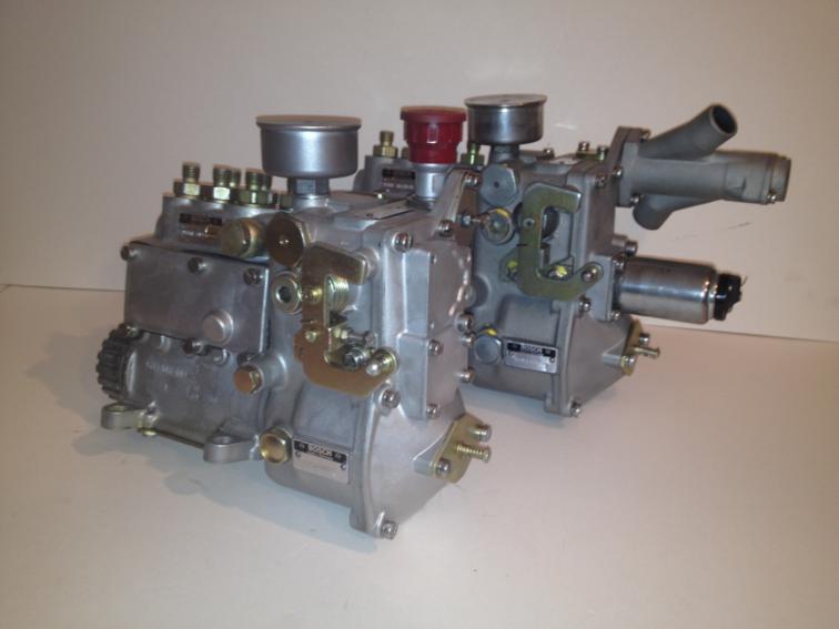
The mechanical fuel injection system used by Porsche on the 911 was only in production from 1969 until 1973. As a result even the last of the pumps produced are now nearly forty years old. Over this time fuel deposits inside the pumps have hardened and contaminants in the oil have damaged the bearings and seals.
.
In addition, given that hardly any service garages understand how the system works, this often leads to tampering with the factory settings or poor repairs being made.
.
Many owners have pumps that they can’t get to run properly and leak oil over their engine, fuel into their engine oil, or both, but find the cost of having their pump restored and calibrated by a specialist prohibitive.
.
This book aims to provide you with the information needed, for you to tackle the job yourself, at home.
.
A mystique has grown up around Porsche’s MFI system, many believing the repair and calibration of the pump to be beyond the skills of the ordinary home mechanic. I am not one of those who believe that to be true, so I have written this book to prove it. I believe anyone with a reasonable amount of mechanical skill and access to normal servicing tools can repair these pumps and if you are willing to take the time and invest in some simple equipment you can also do the calibration work at home as well.
.
Very little information is available on the repair or the calibration of these injection pumps and what information is available is in German and set out in a highly technical manner, having been written for internal use by Bosch technicians familiar with the pumps and servicing equipment.
.
For this reason, I have drawn together the information available and have added my experience of repairing these pumps to produce a user-friendly step-by-step guide suitable for use by the home DIY mechanic. Hundreds of photos are included, as these are often easier to understand than written descriptions of the tasks. Where required I have included diagrams and drawings of the tools you may need to make.
.
.
Where I have made reference to the Bosch data sheets, I have explained clearly how to read the data and how the measurements or readings relate to your pump.
.
.
By following this book, I am confident you will be able to successfully repair and calibrate your pump, and have the satisfaction as I did of knowing you did it all yourself.
.
.
As you can see from the contents page below, the book is extensive, yet simple to follow, taking you through every aspect of dismantling, cleaning, rebuilding, calibration and more......
.
.
| Contents | ||
| About the author | 3 | |
| Acknowledgements | 4 | |
| Introduction | 5 | |
| CHAPTER 1: | How the system works | 7 |
| CHAPTER 2: | Tools and equipment | 9 |
| CHAPTER 3: | Removing the pump from your car | 11 |
| CHAPTER 4: | Dismantling your pump | 13 |
| CHAPTER 5: | Cleaning, inspection and repair | 52 |
| CHAPTER 6: | Rebuilding the pump | 65 |
| CHAPTER 7: | Rebuilding the compensator | 85 |
| CHAPTER 8: | The governor and final assembly | 94 |
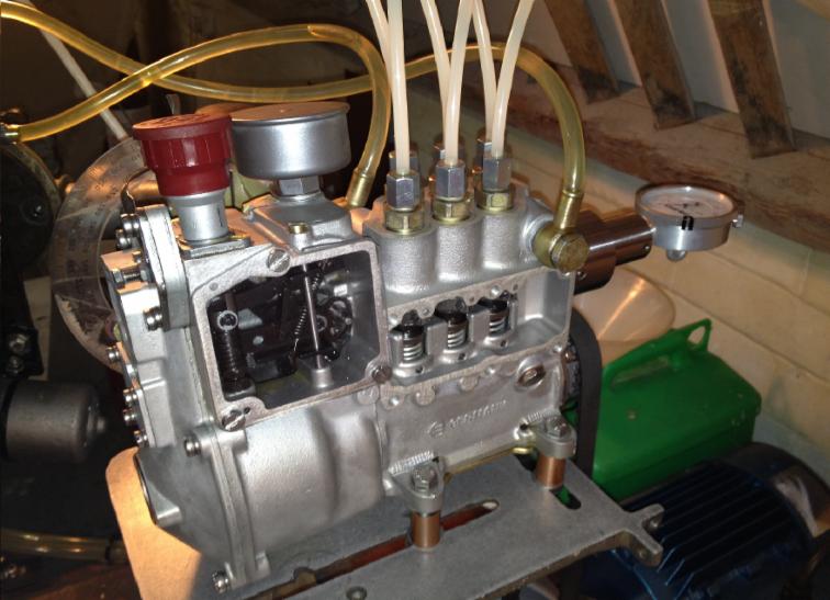
| CHAPTER 9: | Building a test rig at home | 122 |
| CHAPTER 10: | Preparing your pump for testing | 135 |
| CHAPTER 11: | Testing and calibration | 139 |
| Appendix | Bosch data sheets | 146 |
.
Below is a snip-it from the book from Chapter 6 - Rebuilding the pump. Here you can see how the step-by-step guide takes you through each step, followed up with pictures of what you will be doing. Please note that the photos in the book are in black and white.
Rebuilding the Pump
Now that you have all your parts clean and have identified and replaced, or repaired, any damaged or worn parts, its time to put the pump back together.
Start by screwing in the blanking plug for the fuel chamber if you took them out. Apply a thin film of fuel resistant gasket sealant to the threads.
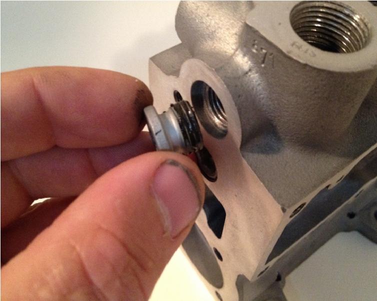
Press a new seal into the rear bearing housing. Press the seal down so it sits flush with the outer flange face. A large socket can be used to do this, tapping the seal down with a mallet or using a press. It is a good idea to smear a little sealant around the edge of the seal as this helps it slip into place and seals it to the housing.
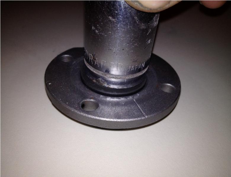
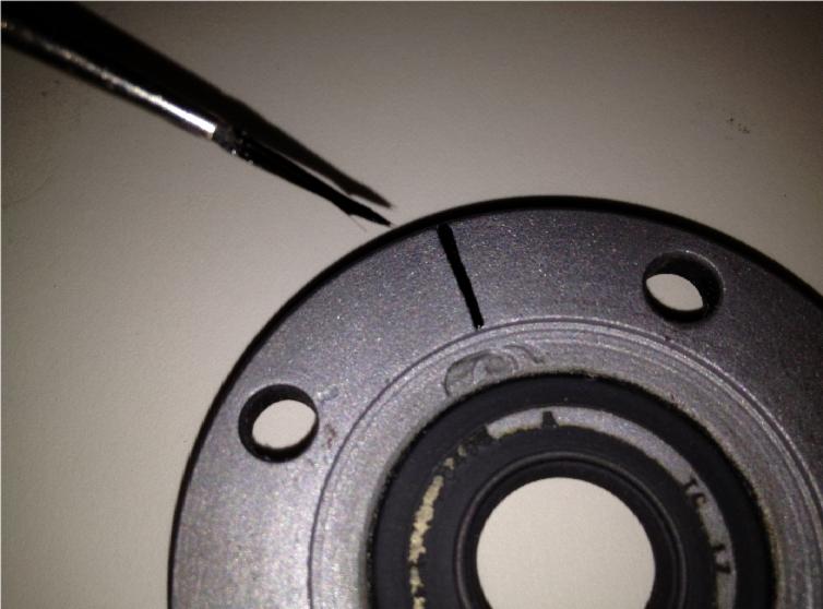
Taking a fine modelling paintbrush, paint the alignment line, so you can see it better later when you are putting the pump back on your car. If you are having the pump black then paint the line white as original. If you have had the housing zinc plated, as in the photo, then paint it black so it contrasts better.
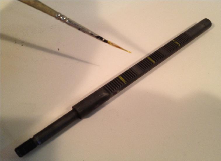
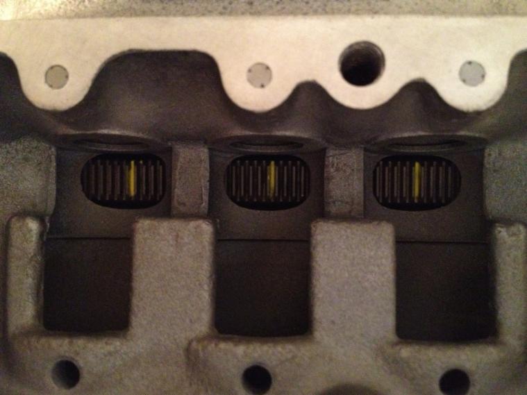
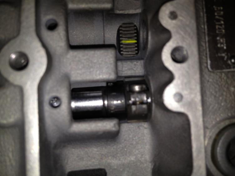
While you have your brush out, paint a yellow line at the centre of the rack for each gear segment. Find this by counting in from both ends for cylinders 2 and 5. You can see that this is the 7th gap from either end. Then counting out from the centre again, mark the same 7th gap for cylinders 1,3,4 and 6.
Now you can feed the rack into the pump body from the driven end.
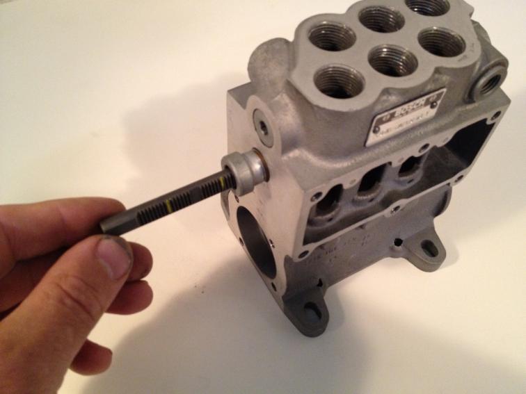
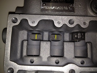
Lay the pump down on its side so that the chambers for cylinders 1,2 and 3 are facing up. Now rotate the rack until the gear segments line up with the openings in the pump housing and centre up the yellow lines. You can see that without the markings it is difficult to see where the rack is in relation to the pump body. This method avoids the need to use the Bosch centring tool and a DTI from the driven end.
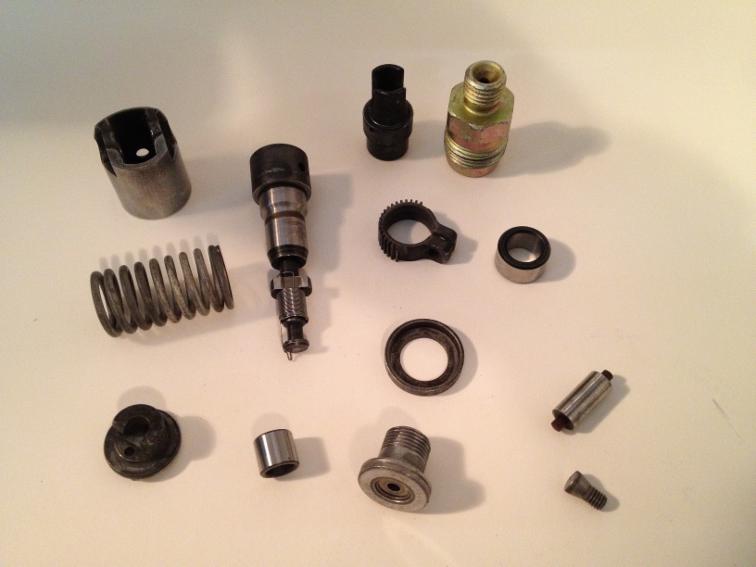
Take out the piston components for number 1. If you have kept it all together you should have a piston and barrel set, piston seat, gear segment, clamping screw, spring, control sleeve, roller follower body, outer roller, inner roller, roller centre shaft, delivery valve, a new nylon sealing washer (not shown) and delivery valve holder.
Take the gear segment and place it onto the rack in the opening for number 1. The segment is correctly located when it is facing directly out at 90 degrees to the rack. You can use the yellow lines in the other openings to help locate the gear. There is only one position where the gear segment is set into the rack at the right position. One tooth out, either way, and the segment will not look right.
When the control sleeve is fitted the holes in the base of the sleeve must face outwards. You are going to feed the sleeves into the gear segments while in the pump housing but the photo shows how it should look once installed.
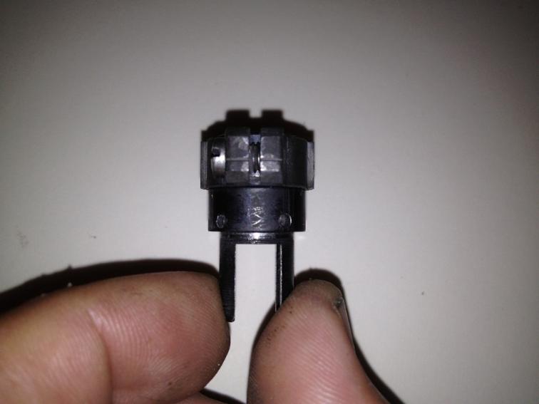
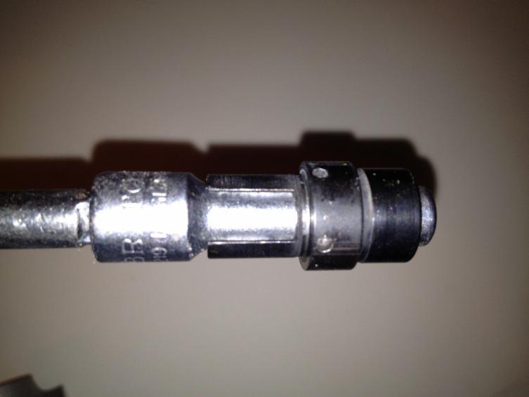
To insert the sleeves, I place them onto a Britool 7/32 deep reach socket on a 1/4 drive extension. This allows you to feed the sleeve into the gear segment from inside the pump body. If you don’t have a suitable socket and extension you can have a 14mm diameter bar turned down at the end 30mm to 9mm diameter instead.
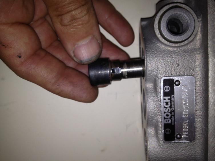
Holding the gear segment steady and engaged correctly with the rack, push the sleeve into the segment until the shoulder is seated against the gear.
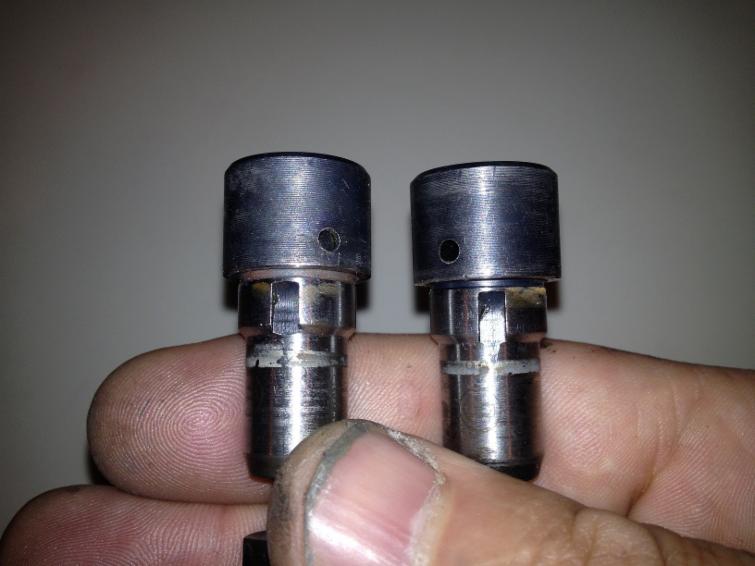
Hopefully you have put your pistons with their matched barrels into numbered compartments in your trays, so you can now put them back into the right chambers in the pump. You will see that the barrels are handed. Those on the right in the photo below are for cylinders 4, 5 and 6, the hole in the barrel for the fuel to flow through being on the left of the alignment notch.
Push the barrel into the chamber with the notch facing out. This way the small pin in the pump body will engage with the notch aligning the barrel correctly.
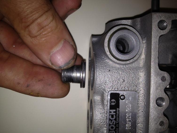
The non-return delivery valve is then fitted to the top of the barrel. The seal made between the base of the delivery valve and the barrel relies on the close-machined surfaces. Do not be tempted to put sealant between the faces. The tolerances are such that the faces will seal on their own. The thickness of the film of sealant will make leaking of fuel back into the pump more likely and will most probably clog the valve and later the injector………………….
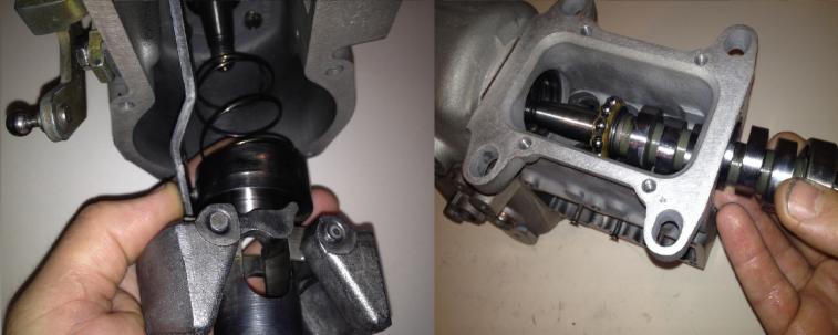
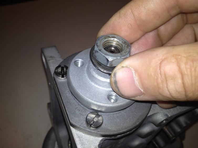
From page 84……………………….The pulley mounting is secured with a crinkled washer and nut. This is torqued down to 49 N-M or 5.0 kgf.m. Lock the cam still using the brace detailed earlier, bolted to the pulley mounting and held in a strong vice.
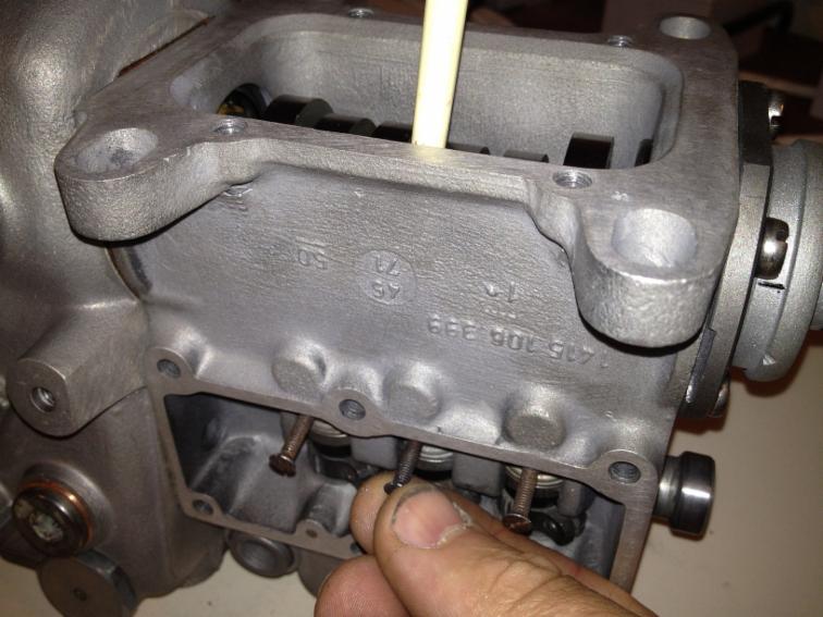
Now with the cam in place, you can release the roller followers. Turn the pump upside down and using a 10mm diameter wooden dowel press the followers up one at a time. With the springs depressed, take out the 3.5mm holding pins or screws. To get to each follower you will need to turn the cam, so that the lobe is facing away from the roller follower, giving you access from underneath.
With all the pins out, turn over the cam and see that all the followers and pistons move freely up and down and that the cam does not bind up. Put a few drops of oil onto the cam lobes to let them run smoothly. Then you should be able to turn the cam with little effort.
Now move the rack to full load and let go whist turning the cam. See that the rack still moves freely back to stop. In general the movement of the pistons in their barrels tends to assist the return of the rack to stop, so if it was a little hesitant before, this may now be gone.